STEP Files
What Is a STEP File? (.STEP / .STP Explained)
A STEP file is the standard, vendor-neutral way to exchange 3D CAD models between different programs. What it contains, how it differs from a mesh, and which version to use.
On this page
- What does STEP stand for?
- .STEP vs .STP: is there any difference?
- B-Rep: why STEP geometry is exact
- What a STEP file contains — and what it doesn’t
- Real example: what is inside an assembly STEP file
- AP203, AP214 and AP242
- Where STEP is used
- Which software opens STEP files?
- Advantages of STEP
- Limitations to keep in mind
- Tips before you send a STEP file
- Frequently asked questions
In short
- A STEP file (
.stepor.stp) is a 3D CAD model saved in the international standard ISO 10303, so it can move between different CAD programs. - It stores exact geometry (B-Rep solids and surfaces), assembly structure, units and, depending on the version, colors and manufacturing annotations.
- It does not store the design history: you get the finished shape, not the steps used to model it.
If you work with suppliers, machine shops or customers who use a different CAD system than you, STEP is very likely the format you exchange. STEP is a neutral 3D format widely supported by major CAD and CAM systems, and it is one of the most commonly used formats for exchanging geometry with machine shops, suppliers and manufacturing systems.
What does STEP stand for?
STEP stands for Standard for the Exchange of Product model data. It is the informal name of ISO 10303, a family of international standards published by ISO whose first parts appeared in 1994. The goal is simple to state and hard to achieve: describe a product’s data in a neutral way, independent of any CAD vendor, so that systems that implement the standard can read it.
ISO 10303 is not a single document but many “parts”. Two of them matter most in daily work:
- Part 21 (ISO 10303-21) defines the plain-text file format — the actual
.stepfile you send by email. - The Application Protocols (AP203, AP214, AP242…) define what information the file can carry for a given industry or use case.
.STEP vs .STP: is there any difference?
No. .step and .stp are two extensions for the same format; the content is identical. The short version exists because older operating systems limited file extensions to three characters. The US Library of Congress format description lists the .stp, .step and .p21 extensions. You may also see .p21 (after Part 21) and compressed variants such as .stpZ.
Because STEP files are plain text, you can open one in a text editor. These are the real first lines of as1-oc-214.stp, the sample assembly we use in our tests (load it with Try a sample in the converter and download it with Original STEP):
ISO-10303-21;
HEADER;
FILE_DESCRIPTION(('Open CASCADE Model'),'2;1');
FILE_NAME('Open CASCADE Shape Model','2008-07-24T15:00:20',(
    '--- Datakit Converter ---'),('--- Datakit www.datakit.com---'),
  ' Release Version  Jun 30 2008','Open CASCADE 6.1',' ');
FILE_SCHEMA(('AUTOMOTIVE_DESIGN { 1 0 10303 214 1 1 1 1 }'));
ENDSEC;
DATA;
#1 = APPLICATION_PROTOCOL_DEFINITION('international standard',
  'automotive_design',2000,#2);
...
#7 = PRODUCT('as1','as1','',(#8));
...
Three useful things can be read without opening any CAD software:
FILE_NAMEstores the export date and the system that produced the file: here, the Datakit converter with Open CASCADE 6.1, on 24 July 2008.FILE_SCHEMAtells you the protocol:AUTOMOTIVE_DESIGNis AP214,CONFIG_CONTROL_DESIGNis AP203 and a schema starting withAP242is AP242.- The
DATAsection is a list of numbered entities that reference each other. Entity#7, for example, is the productas1, the top-level assembly.
A complete STEP file always ends with the line END-ISO-10303-21;. If it is missing, the file has probably been cut off; see what to do when a STEP file won't open.
B-Rep: why STEP geometry is exact
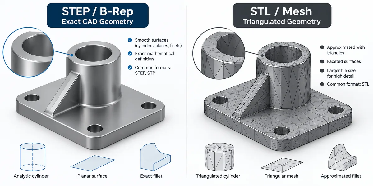
Most STEP files describe parts with B-Rep (boundary representation). A solid is defined by the surfaces that bound it: each face lies on a mathematical surface (a plane, a cylinder, a cone, a sphere, a torus or a free-form B-spline/NURBS surface) and is trimmed by edges and vertices. The topology records how faces connect into closed shells and solids.
The practical consequence is precision. A 10 mm hole in a STEP file is a real cylinder with a 10 mm diameter, not a ring of flat triangles. That is why STEP can be used to machine a part, program a CNC toolpath or check a fit — and why it is very different from mesh formats such as STL or OBJ.
One detail that surprises people when they open a real STEP file: the same shape can be written in different ways depending on the exporting software. as1-oc-214.stp contains no CYLINDRICAL_SURFACE entity at all; the round faces of the rod and the bolts are stored as 28 rational B-spline (NURBS) surfaces, alongside 25 planar faces. The geometry is still exact, because a rational NURBS can represent a circle with no error, but another program would have written those same faces as cylinders. For the person receiving the file the result is equivalent; the difference only shows if you inspect the text or if a program recognises one form better than the other.
| STEP (B-Rep) | STL / OBJ (mesh) | |
|---|---|---|
| Geometry | Exact surfaces and edges | Triangles approximating the surface |
| A cylinder is… | A true cylinder with a radius | Many flat facets |
| Assemblies | Yes, with part names and positions | STL: no; OBJ: groups only |
| Units | Stored in the file | STL has no units |
| Typical use | Design exchange, manufacturing | 3D printing, visualization |
What a STEP file contains — and what it doesn’t
Depending on the exporter and the protocol, a STEP file can include:
- Solids and surfaces with their exact geometry.
- Assembly structure: which parts make up the product, their names and their positions.
- Units (millimeters, inches…).
- Colors and layers, per part or per face (AP214 and AP242).
- PMI — product and manufacturing information such as dimensions and geometric tolerances attached to the 3D model (AP242).
- Product metadata such as part names and descriptions.
What it usually does not include is anything specific to the program that created the model:
- The feature tree (sketches, extrusions, fillets, patterns as editable operations).
- Parametric constraints and design intent.
- Assembly mates as working relationships.
- 2D drawings — those are normally exchanged as PDF or DWG/DXF.
This is why engineers sometimes call an imported STEP model a “dumb solid”: the shape is right, but the recipe is gone.
Real example: what is inside an assembly STEP file
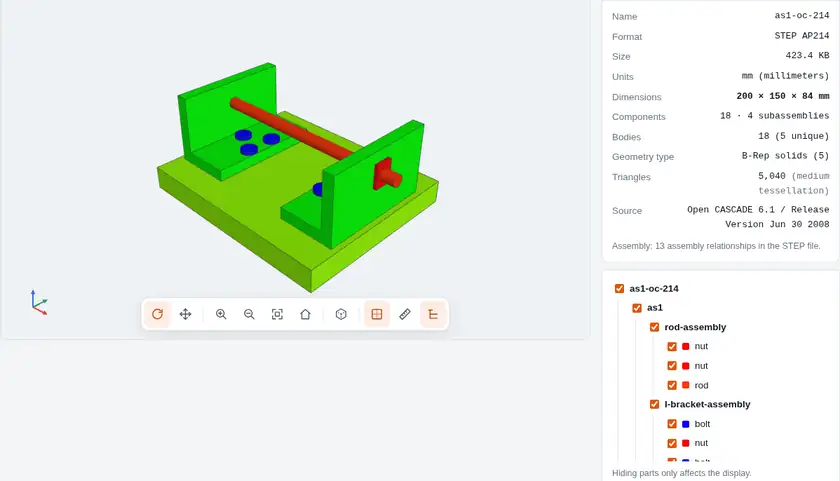
To keep this from staying theoretical, we counted the entities in as1-oc-214.stp, a public test assembly of 433,606 bytes (8,362 lines of text). It is a bracket with a base plate, two L-brackets, a Ø10 × 200 mm rod and its fasteners.
| What is counted | STEP entity | Count |
|---|---|---|
| Entities in the DATA section | all | 6,425 |
| B-Rep solids | MANIFOLD_SOLID_BREP | 5 |
| Faces | ADVANCED_FACE | 53 (25 planar, 28 rational B-spline) |
| Edges | EDGE_CURVE | 126 |
| Vertices | VERTEX_POINT | 84 |
| Coordinate points | CARTESIAN_POINT | 3,506 |
| Products (parts and subassemblies) | PRODUCT | 9 |
| Assembly relationships | NEXT_ASSEMBLY_USAGE_OCCURRENCE | 13 |
| Colours | COLOUR_RGB | 2 |
More than half of the entities are points: exact geometry takes space too, because every B-spline surface is defined by its grid of control points.
5 solids, 18 parts on screen
The file defines only five distinct shapes: nut, bolt, rod, l-bracket and plate. The 13 assembly relationships reuse them in different positions: each bolt-and-nut pair is a subassembly (nut-bolt-assembly) placed three times on each L-bracket, and the complete L-bracket is placed twice. Expanding the tree gives 18 parts: 8 nuts, 6 bolts, 2 L-brackets, 1 rod and 1 plate. It is the same principle your CAD software uses: a part is defined once and inserted many times.
Units and validation properties
Units are not guessed: the file declares SI_UNIT(.MILLI.,.METRE.), i.e. millimetres, with length tolerances of 0.000005 and 0.00001 mm depending on the geometric context. The exporting program also stored geometric validation properties for each product: volume, surface area and centroid. They let the importing system check that it read the file correctly. In this example:
- The rod declares a volume of 15,708.37 mm³. A Ø10 × 200 mm cylinder has π × 5² × 200 = 15,707.96 mm³: they agree within 0.003%.
- The sum of the 18 parts (8 × 664.37 + 6 × 3,200.72 + 15,708.37 + 2 × 96,858.57 + 530,574.97) gives 764,519.8 mm³, the same volume the file declares for the complete assembly.
Not every program writes these properties, but when they are present they are a quick way to verify a translation. In our comparison of STEP, STL and 3D PDF with the same model we use those same volumes to measure how much is lost when converting to a mesh.
AP203, AP214 and AP242
When you export STEP, most CAD programs ask you to choose an Application Protocol. They define which kinds of data the file may carry:
| Protocol | Official scope | In practice |
|---|---|---|
| AP203 | Configuration controlled 3D design of mechanical parts and assemblies | The oldest widely used protocol. Geometry and assembly structure; its original edition carried no colors or layers. |
| AP214 | Core data for automotive mechanical design processes | Despite the name, widely used outside the automotive industry. Adds colors and layers. A very common default export. |
| AP242 | Managed model-based 3D engineering | First published in 2014 to unify AP203 and AP214; the current edition is ISO 10303-242:2025. Adds semantic PMI (GD&T) and tessellated geometry. The recommended choice for new work when the receiver supports it. |
A reasonable rule: if you don’t know what the other side uses, AP214 is widely compatible; choose AP242 when you need 3D annotations or when the receiver asks for it.
Where STEP is used
Engineering collaboration
Companies rarely share the same CAD system. Modern versions of major CAD systems such as SolidWorks, CATIA and Siemens NX generally support STEP import and export, so it often becomes the common language for design reviews and interface checks between parts.
Manufacturing
Machine shops, sheet-metal fabricators, mold makers and 3D printing services usually ask for a STEP file with the quote request. Because STEP preserves precise CAD geometry, it can often be imported into CAM software as the basis for generating toolpaths.
Component catalogs
Manufacturers of standard parts — bearings, fasteners, motors, pneumatic components, connectors — publish downloadable STEP models so designers can drop them into their assemblies whatever CAD they use.
Which software opens STEP files?
Most professional mechanical CAD systems can import and export STEP; the exact options depend on the version and license. Some common examples:
| Software | Type | STEP |
|---|---|---|
| SolidWorks | Commercial CAD (Dassault Systèmes) | Import and export |
| Autodesk Inventor | Commercial CAD | Import and export |
| CATIA | Commercial CAD (Dassault Systèmes) | Import and export |
| Siemens NX | Commercial CAD | Import and export |
| PTC Creo | Commercial CAD | Import and export |
| FreeCAD | Free, open-source CAD | Import and export |
| STEP viewers | Desktop or online, view only | Open, inspect, measure |
You don’t need a full CAD license just to look at a model. If you only need to see it, measure it or check its parts, a viewer is enough — the options are compared in how to open a STEP file without SolidWorks.
Advantages of STEP
- Vendor-neutral: an ISO standard, not owned by any CAD company.
- Precise geometry (B-Rep), a common basis for manufacturing and inspection.
- Assemblies with part names and structure.
- Widely supported by commercial and free CAD, CAM and viewers.
- Plain text, readable decades later without the original software.
Limitations to keep in mind
- No design history: editing means working on the solid or remodeling features.
- Translation issues can happen: small gaps between faces, tolerance differences or surfaces that arrive as open shells instead of solids.
- Colors, names and PMI depend on export options and on what the receiving program supports.
- Size: large assemblies produce big text files, heavier than native formats.
- The recipient still needs software that can read it. For people without CAD, a format they can already open — like a 3D PDF — is often easier. See how to share a 3D CAD model without CAD software.
Tips before you send a STEP file
- Pick the protocol on purpose: AP214 for broad compatibility, AP242 if annotations matter.
- Check the units in the export options, especially between metric and imperial companies.
- Export assemblies as a single file unless the receiver asked for one file per part.
- Open the exported file in a viewer before sending it: confirm that all parts are there, that it is a solid and that the size is right.
- Remove what you shouldn’t share: internal parts, supplier components or details not needed for the quote.
If the person receiving the model only needs to look at it, consider sending an interactive 3D PDF alongside the STEP. What a 3D PDF is and how it works explains when that makes sense.
Frequently asked questions
Is a .stp file the same as a .step file?
Yes. Both extensions are used for exactly the same format. .stp is simply the three-letter version, common because older systems limited extensions to three characters. You can rename one to the other without changing anything inside.
Can I edit a STEP file?
You can import it into a CAD program and modify the geometry, but you won’t get the original feature history (sketches, extrusions, fillets as editable steps). You work on the resulting solid with direct-editing tools, or rebuild the features.
Is STEP a mesh format like STL?
No. STEP normally stores exact geometry (B-Rep): real planes, cylinders and free-form surfaces with precise dimensions. STL only stores triangles that approximate the surface. A STEP file can be converted to a mesh; going back from a mesh to exact geometry is much harder.
Is STEP better than IGES?
For solids and assemblies, generally yes. IGES is older and was designed mainly around curves and surfaces, so solids and assembly structure often arrive incomplete. STEP handles solids, assemblies, colors and (in AP242) PMI more reliably. IGES is still useful for some surface-modeling workflows and older systems.
Can I open a STEP file without CAD software?
Yes. A STEP viewer — installed or in the browser — is enough to rotate, measure and inspect the model. See how to open a STEP file without SolidWorks for the options.